Experiment 3
Turning the Knob: Potentiometers1
Analog and Digital.
We are all familiar with the term digital
- digital camera
- digital computer
- digital watch
- digital thermometer
Digital devices are those whose internal representation of the data is expressed as a series of zeros and ones. For example, the word hello is represented within a computer as
01101000 01100101 01101100 01101100 01101111
One key aspect of digital devices is that there is nothing between zero and one. For example, you can’t have 0.25 or 0.5. In contrast, an analog device has continuous values, meaning you can have a number like 127.33333333333333 and the slightly bigger number, 127.333333333333331, Another example in the analog world, is an analog sine wave which looks like:
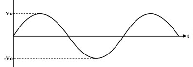
See how nice and curvy that wave is?
Digital computers would be less useful if they couldn’t represent numbers like 127.33333333333333, $12.25 or a sine wave so they approximate the analog value. For a sine wave the digital approximation might be:
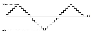
It is a close approximation but not exact.
If you go hear a musical group live, or listen to the group on vinyl, you are hearing analog sound similar to that nice smooth sine wave above. Compact Discs (CDs) invented in 1982, are digital representations of music. They are like the chunky sine wave above. Audio aficionados criticized the lack of nuance of these compact discs. For example, instead of a continuous volume scale there are now discernible steps. The criticism grew more intense with the introduction of MP3s, another digital format.
When we have been using LEDs, we’ve been turning them either on or off (a digital 0 or 1), and not ⅔ or ¾ on. To turn them on and off we have been using digitalWrite.
In the previous experiment we have been working with buttons, which also are digital devices. They are either on or off. They can’t be ⅔ or ¾ on. So for buttons we used digitalRead.
Somewhere in your life, you have experience with a real volume knob. A real volume knob is continous. It can have values like ⅔ or ¾. For those, we can’t use digitalRead. Do you have a guess as to what we do use?
If you are thinking analogRead you would be 99.44% correct!
When we have been connecting LEDs and buttons to our Arduino Uno we have been using the pins labeled digital. If you look at the other side of the board you will notice pins labeled Analog In. These are the pins we will be connecting our analog devices to, like a volume knob.
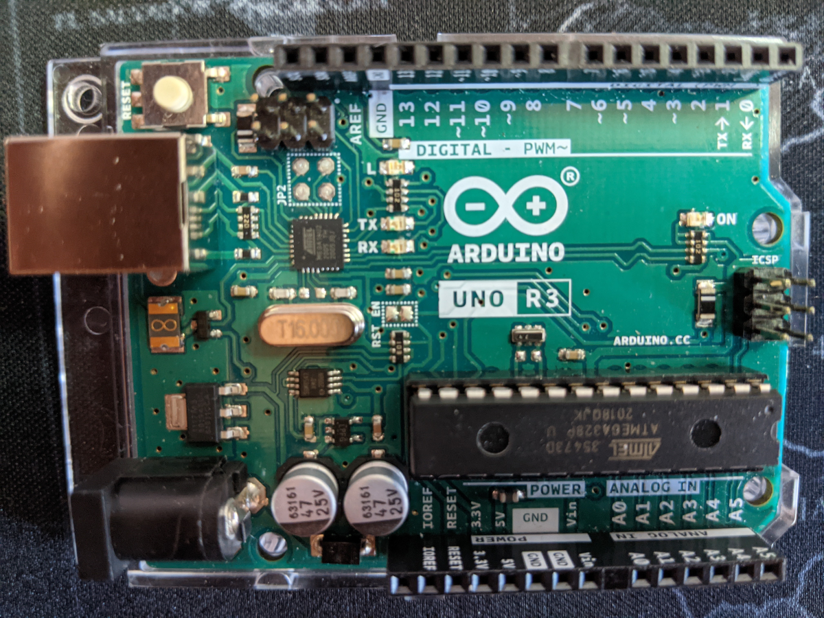 Side view:

The rub
The Arduino Uno is a digital computer meaning that internally, data is represented in discrete steps. A volume knob is an analog device meaning we can infinitely adjust it. When we connect a knob to the Arduino it approximates the continuous volume of the knob (the picture on the left) in discrete steps (the picture on the right).
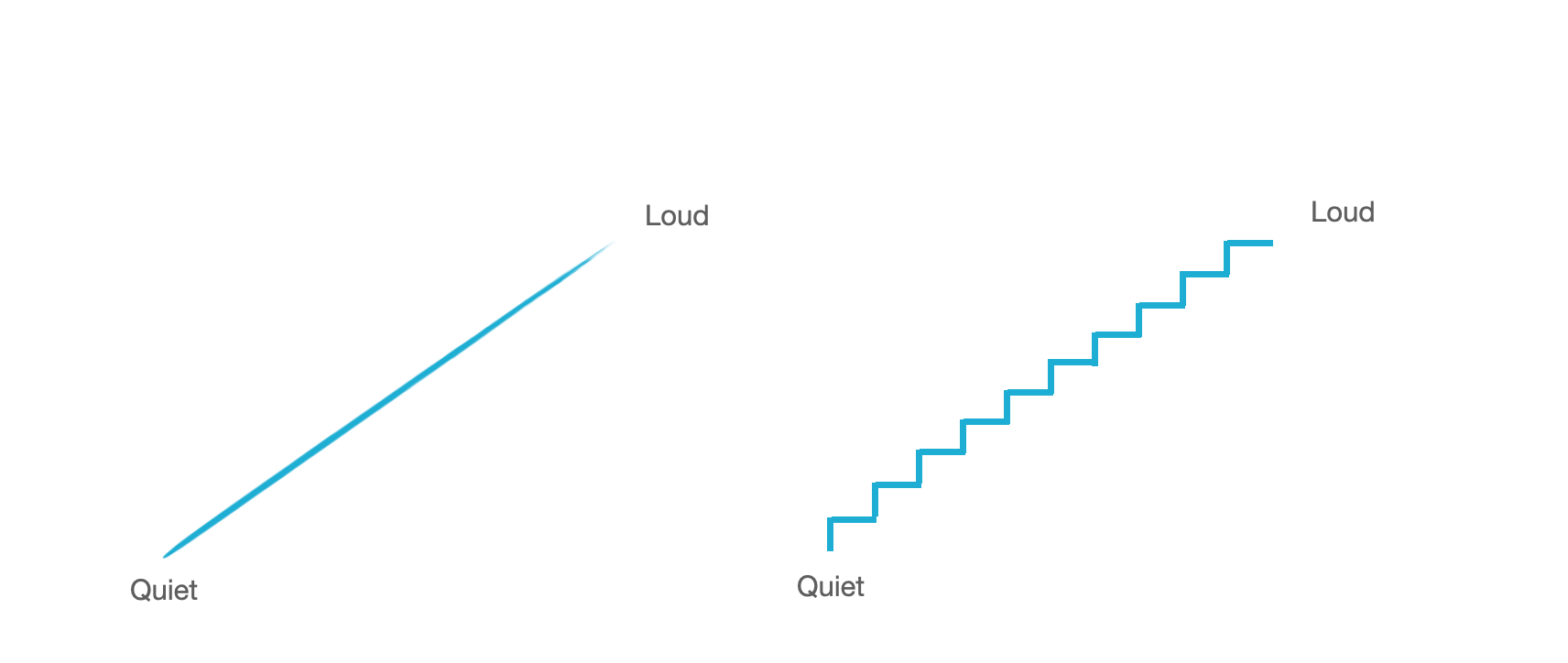
Different computers have different numbers of steps. The range for the Arduino Uno is 0 to 1023. So, for example, the analog read of the knob can be 512 or 513 but not 512.25 and the lowest it reads is 0 and the highest 1023.
Introduction to the experiment
In this experiment we will be working with the equivalent of a volume knob, the potentiometer (aka a variable resistor):
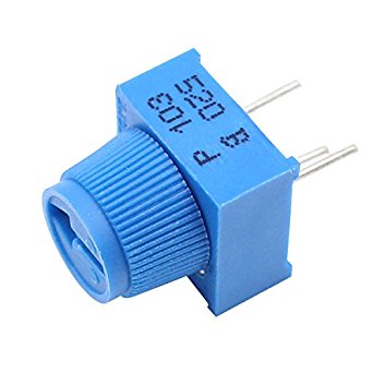
Beautiful, isn’t it? Potentiometers come in all sorts of shapes and sizes. The one in your kit might come in two pieces as shown on the left, that are put together as shown on the right:

When the outer legs of the potentiometer are connected to ground and 3V (V stands for volts)the middle pin outputs a voltage between 0V and 3V depending on the position of the knob on the potentiometer.
Parts Needed
You will need the following parts:
- 1x Potentiometer
- 1x LED
- 1x 330 ohm Resistor
- jumper wires

Hardware Hookup
Add the potentiometer to the same LED circuit from the first experiment. Follow the Fritzing diagram below.
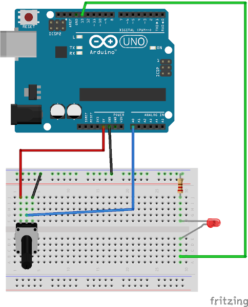
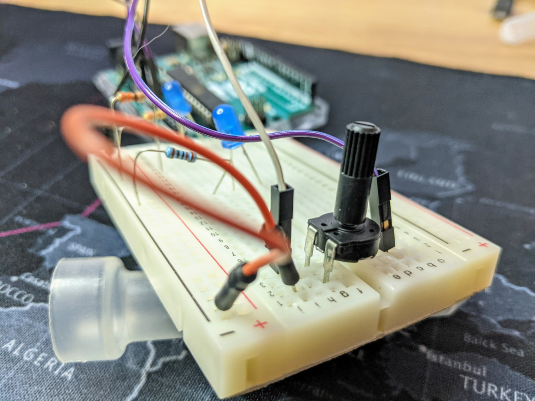
When I constructed the circuit I had the potentiometer go across the valley with the outer legs on one side and the inner leg on the other.
The code
Copy and paste this code into the IDE. Then upload.
int pot = A0;
int led = 13;

// the setup routine runs once when you press reset:
void setup() {
  // initialize serial communication at 9600 bits per second:
  Serial.begin(9600);
  pinMode(led, OUTPUT);
}

// the loop routine runs over and over again forever:
void loop() {
  // read the input on analog pin 0:
  int sensorValue = analogRead(A0);
  Serial.println(sensorValue);
  //
  // NOW BLINK
  digitalWrite(led, HIGH);
  delay(sensorValue);
  digitalWrite(led, LOW);
  delay(sensorValue);
}
Notice that the value of the potentiometer is printed to the serial monitor. If the circuit doesn’t work, check out the serial monitor to see if you are getting a range of values close to 0 to 1023.
What You Should See
You should see the LED blink faster or slower in accordance with your potentiometer. If it isn’t working, make sure you have assembled the circuit correctly and verified and uploaded the code to your board. The potentiometers that come with these kits are sometimes finicky and sometimes pop out of the breadboard.
A short explanation
In this line:
int sensorValue = analogRead(A0);
we instruct the Arduino Uno to read the value coming from the potentiometer (pot for short) and save the value in a variable called sensorValue. The potentiometer will be outputting an output voltage between zero and 5 volts. The Uno converts this to an integer between 0 and 1023 inclusive. When the potentiometer is in the ‘off’ position and is outputting 0 volts (or 0V) the Uno will read 0. When the pot is turned all the way on, the Uno will read 1023.
The variable named sensorValue is set to whatever the Uno reads from the pot. When that value is large, say 1023, the LED will blink slowly (on for 1 second and off for 1 second) and when the value is small it will blink rapidly– so rapid that it is imperceptible.
REMIX:
Remix 1: Something completely different
Suppose we want to do something completely different. When the potentiometer is turned to the low end, the LED will be off, when it is turned to the high end it will blink. To implement this we need to be a bit more specific. Since the entire range is 0 to 1024, suppose we design the code so that if sensorValue is below 512 the LED will be off and if it is above that the LED will blink. Any clues on how to do this?
A hint
If you are thinking this sounds like a job for an if` statement, you would be correct. Maybe something like
if (sensorValue < 512){
       // shut the LED off
  }
  else {
       // blink
  }
Remix 2: a Challenge
Suppose I want the potentiometer to do 3 things. When it is in the lower third of its range the LED is off; when it is in the middle third the LED is blinking; and in the upper third it is steadily on. Can you modify the code to do this?
hint
The structure might be like
if (something){
     // do one thing
  }
  else if (something){
    // do another thing
  }
  else {
    // do a third thing
  }
Remix 3: Bike Light Challenge
Can you implement the device illustrated here
Initially, when the potentiometer is all the way to the left all lights are off. As you move it to the right, it changes to different modes. Can you duplicate this? Feel free to use your own interesting patterns.
1: This experiment is a remix of Sparkfun’s Reading a Potentiometer.